Commodore 64 disk drive programming

The Commodore c64 is a computer where the Kernal (the OS if you will) supports load and store on tape and disk. The tape is a directly connected device where the Kernal provides all the code to steer the units mechanics, and parse the pulses to and from it. The disk drive is a lot more complex, and the connection here is via a serial bus. This is like communicating with another computer – the 1541 disk drive IS basically like another computer. It has it’s own CPU (a 6502), two 6522 VIA circuits (like the 6526 CIAs in the C64 itself – here accessible on $1800 and $1c00), 2KB of RAM ($0000 to $07ff), and 16KB of ROM ($c000 to $ffff).
So thinking of the disk drive as a separate computer, you can communicate with it and you can program it pretty much like the c64 itself.
My own master reference to the disk drive is the book “Inside Commodore DOS” (LINK) by Richard Immers and Gerald G Neufeld. I will take the liberty of extracting a few pieces from it in the following.
Key understandings
Disk organisation – the physical level
When you format the disks, you establish the track and sector structure on it, so that the DOS in the drive has space where it can store data. The normal DOS uses 35 tracks where the outer (1 to 17) have 21 sectors and the inner ones gradually fewer. This is needed as the distance round trip and the associated magnetic area is getting shorter the closer to the centre of the disk you get. It could also be mentioned that the 1541 doesn’t use the sync hole of the disk (as the PC does). This means that the 1541 doesn’t know where on the track it is. On one track, sector 0 can be 12 o clock, but on the next, it could be at 3 o clock.

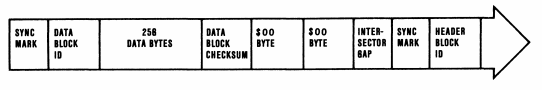
On the physical layer, the disk block has a header block preceding the data block.

Going to the details of the two types, the header contains sync marks and then header data.

The data block structure is as follows:
Disk organisation – the logical level
As per the previous section, formatting a disk, the DOS establishes 683 blocks to be used. Track 18 is special; this is the directory track, and this is why we see 664 blocks free on a new disk after track 18 has been allocated for disk management. And it could be noted that using the track in the middle for the directory is quite smart. The average number of track the stepper needs to move to get there is as small as possible if the directory track is in the middle.
Filestructure
A file (PRG, SEQ and USR) is stored in the 256 byte blocks of a sector in the form of two bytes that point to the next track/sector of the file and then 254 bytes of data. The last sector of a file uses $ff as track, to mark the end, and then the sector value is denoting the number of bytes used in the sector. Anything after the last byte in use is not part of the file – it’s wasted storage space. But you can of course hide data there if you want to.
In the first sector of a PRG file, the first two data bytes define the load address of the file. So here we have track, sector, load low, load high and then 252 bytes of real file data. This is rather the file format than the disk format, but might be relevant to mention anyway. SEQ and USR are plain data formats with no part of the file being assumed to have any specific meaning.
One could also mention that files are not placed on the adjacent sectors on the track (1,2,3,4 etcetera). It’s rather 1,11,21. The number of sectors skipped is called interleaving and the reason for this is to optimise the process. The drive needs time between fetching the first sector before it is going to fetch the next, and you typically eliminate the risk for the drive to make a full new lap to find the next sector of the block chain. A hundred times better way would have been if Commodore would have populated the drives with enough RAM for reading a full track to RAM, as some of the parallel speeders have it. But they didn’t and it’s somewhat too late to fix that now …
Block Allocation Map (BAM)
Track 18 ($12), sector 0 is the Block Allocation Map (BAM). That is the systems storage space for telling what blocks are available for storage, and what has been occupied. This is also where the disk name and the disk id is stored.
The directory
The rest of the sectors on Track 18 ($12) – starting with sector 1 is the Directory.
Here, each entry uses 30 bytes, stored in eight 32 byte groups inside a sector.
Byte 0 and 1: So if we assume that each entry is 32 bytes, the first two bytes of the first entry is a pointer to the next track/sector of the directory chain, as for files. In the other seven entries of that sector, these are just two bytes that hold zero. They are unused and can be seen as padding.
Byte 2 is the file type and here we must enter bit level to understand the value.
Bit 7 indicates a closed file, and if this is zero then it’s unclosed. On the directory, you see this marked with an asterisk (“*”)
Bit 6 indicates replacement which is a state the file has during a save and replace operation (which is a flawed function that you should use with care)
Bit 5 indicate a Locked file. On the directory you see this marked with a bracket(“<“)
Bit 0-2 indicate the actual filetype. In combination with a set bit 7 (closed file) the bits should be interpreted as follows:

Byte 3 and 4: This is the track/sector pointer to the first sector in the file.
Byte 5 to 20: The sixteen chars that forms the filename. There is no marker of the length of the file name. Instead it used inverted spaces for padding ($a0).
Byte 30 and 31: This is the marker for the size of the file. Please mind that this is merely cosmetic – what you see when listing the directory. In the normal case, this should correspond to the number of sectors allocated by the file, but you can change this to anything and there will be impact. File will still occupy the same number of blocks on the disk.
Byte 21 to 29 are not really important in most cases. First three are only used for REL files, next four are unused and then you have two used in the context of save and replace.
Talking to the drive from the computer
There are a number of commands you can issue over the command channel on the serial bus.

So here you can read and write to sectors, read and write to the disk drive ram, you can manage the BAM. A normal use case is that the computer program writes data to the drive RAM (“M-W”) and then run the program (“M-E”), to launch a proprietary communication protocol over the serial bus (like a speed loader). But a fully possible alternative is to use B-E to execute a program that is stored on disk. For most commercial games you would see the M-W and M-E, as then it is possible to encrypt the data, whereas the B-E will need to contain a header that is unencrypted.
You also have the B-R and B-W but these behave very strange and you do best using U1 and U2 instead.
Drive coding – the system way
The internal operation of the disk drive is that is stores jobcodes in addresses polled for jobs, and then the drive reports back on the status of the result in the same job code address. By doing this, you are exposing the full potential but with the full liability. It’s here fully possible that you request the stepper motor to go places where it shouldn’t and that this can – of course – cause problems.
So these are the job commands (basically using the command in the high nibble):

These are the possible results (bascially clearing the job code and storing the result in the low nibble):

Working with the jobcodes, this is a handy table:

So reading the data on track 17, sector 0 to $0400 in the drive you place $80 in address $01, $11 (=17) on $08 and $00 on $09, and then scan $01 for the result.
Drive coding – even closer to the metal
It’s naturally fully possible to skip the overhead of working with job queues and just either call the Kernal routines yourself or write your own DOS. In general, memory is really scarce which makes it quite difficult not to use the drive kernal.
Page 0 is used for storing Kernal values and the job code. If the drive has any sort of access to anything, then it will read and write to portions of this area. There are parts you can use, but this needs to be carefully managed.
Page 1 is allocated by the CPU as it’s a stack mandated by the CPU. If you manage your code, you could ensure that stack usage is kept so that portions of the stack is available for your own code/data.
Page 2 is the command buffer.
Page 7 is allocated for the BAM. You can naturally use this area for storage but be aware that given control to the drive, then this area could be wiped. And there are times when the drive actually looks for stuff here.
So in practice, you are left with page 3, 4, 5 and 6. For reading and writing to the disk, you need one page for the data that goes in and out. Let’s assume you use page 6 for that. This means that your code needs to fit in 3*256 bytes. You need to code efficiently to get something proper done using only this restricted space.
Protections
The whole point with protections is that you bind data to a specific disk. If copied to another disk, the protection check would detect that it’s not sitting on the right disk (by detecting something that isn’t reproduced properly on the copy) and would hence refuse to work. On the computer side, the error checking routine could then be guarded by obfuscation, encryption and checksum to ensure it isn’t disabled or manipulated.
The simple protections are implemented by placing data outside of the general DOS area. Track 36-42 are typically fully accessible by the drive mechanics of the 1541, but it’s not supported by the DOS.
Next step was deliberate format error on the disk. In the early copy program, these errors weren’t copied and would render the copy useless. We saw the advent of more and more complex copy programs (nibblers) and were able to copy more and more complex errors correctly.
But given the hardware restrictions of the c64, not everything can be reproduced. One trick was to place the sync header on one track and then move the stepper to the adjacent track to read the actual data. Given that the 1541 doesn’t have any hardware for reading the sync hole, it is technically impossible to implement a general copier for this scenario.
The countermeasure for copiers was then rather to implement “paramenters”. These are patches to the program in order to eliminate the protection, producing a standard DOS copy where the protection is disabled. This is basically the same as cracking the game, but in the context of a copy program where you need the original to generate the deprotected copy.
Great explanation, but I’m guessing a typo. It says:
“$11 (=17) on $06 and $00 on $07, and then scan $01 for the result”
But don’t you mean “on $08” an “on $09” which are the buffer #1 track and sector?
Correct! Thanks – I have updated that in the text now.
There is only one common misconception:
it is not true that the 1541 can’t write accurately.
It can, if you know what to write.
The real problem when copying was not the writing, but understanding WHAT to write, where and how.
In your example it would be very easy to write SYNCs on a trach and data on another track and then do the opposite when reading.
But for someone that does not know this, it will be “impossible” to copy it because on a track he will read only SYNCs and on another only data and even if he copies both accurately they will never be in sync to each other unless he writes them “knowing” how to write them which in this case will be:
1) write (for example) 3 SYNCs on track #34 and an empty ($55 or %5A) track on track #35
2) wait for a sync on track 34, then move the stepper to track 35 and write the first block.
3) go back to track 34, wait for the next sync and do as point 2.
I agree that you can write this is one a 1541, but what I said was that you cannot make a GENERAL copier for this scenario. One that looks at all the permutations and both reads and writes them properly.
Thanks for this post. Refreshed some memories. Learnt a lot.
1) Shouldn’t the command buffer range not being $200-$2FF (instead of $200-$3FF as found in the corresponding table) as else it overlaps buffer #1 page (300-$3FF)?
2) Could you provide a table with ROM kernel pointers equivalent to job codes or direct access channel commands?
3) Could you propose examples of simple code on how to use the serial channel to launch direct commands (ASM, BASIC) as I understand this is the only way to begin to communicate with the 1541 from a fresh started C64?
4) Any basic hint on how ‘speeders’ work?
5) Any hint on how a program once started on the 1541 usually communicates / works in pair with another one on the C64 (synchronously and/or asynchronously)?
6) Any basic info on the memory mapping of the 2 6522 VIAs ?
1) The text says “Page 2”. The $03FF is surely a typo from the book where the original is from.
2) Do have a look at the link to Inside Commodore DOS.
3) I guess quite a lot of what you look for is this:
https://codebase64.org/doku.php?id=base:dos_examples
4) I do indeed. Do watch my video on that subject:
5) You take over the serial bus and replace the protocol. The video referenced above does explore that. But you can also find any speedloader and have a look. A good one would be this one:
https://github.com/cadaver/c64loader
6) The Inside Commodore DOS has that as well of course. See Page 226 or thereabout (search for 1800 or 1c00)
Bit 6 indicates replacement which is a state the file has during a save and replace operation (which is a flawed function that you should use with care)
Bit 5 indicate a Locked file. On the directory you see this marked with a bracket(“<“)
I think you have bit 6+5 reversed. Bit 6 should be the lock, not bit 5.
will format diskette c64 haben